
Through Thick and Thin: Modelling the Delivery of Non-Newtonian Formulations
24 June 2024
The pharmaceutical industry is currently undergoing a period of rapid innovation, propelled by several factors. These include advancements in the development of biologics, which are becoming increasingly diverse1, decentralized healthcare practices, and a shift towards administering injections less frequently in home settings2. Additionally, small molecules are being designed through AI drug discovery techniques3. While these therapeutic innovations hold promise, they can also bring forth unforeseen challenges in formulation and delivery.
These can include ensuring the stability of large or fragile biologics at higher therapeutic concentrations or improving the solubility of poorly soluble APIs. Overcoming these hurdles can require the implementation of sophisticated solutions such as microcarriers, adjuvants, excipients, and stabilizing matrices4. It’s crucial to recognize that these formulations profoundly impact the physical properties of drugs and can present challenges for parenteral drug delivery, especially in rapid, automated systems like autoinjectors.
One example of this are high-concentration monoclonal antibodies which can experience aggregation under agitation-induced stress. Stabilising matrices composed of polymer, lipid crystal, or polysaccharide gels, offer improved stability and efficacy but can exhibit non-Newtonian flow behaviour. This is also true for long-acting injections composed of particulate suspensions where particle-particle interactions and alignment and result in the same.
The modelling of syringeability and delivery of parenteral formulations has often focused on Newtonian models and the Haggen-Poiseuille equation. While this generally performs well, it is not suitable for predicting the behaviour of non-Newtonian fluids. This is because non-Newtonian fluids do not uniformly thicken or thin as they pass through a needle; rather, this effect occurs near the needle wall where the fluid experiences the highest shear.
For shear-thinning fluids, this phenomenon results in plug-like flow, which can be seen in the dispensation of fluids such as toothpaste. This results in a very different volumetric flowrate at a given pressure. In autoinjectors, this issue is further complicated by the decay of delivery force over the stroke, which is characteristic of most devices powered by springs or gas.
To tackle this challenge, this paper presents an overview of solutions to non-Newtonian fluids described by the power-law, Cross and Carreau models. The aim is to provide a toolbox to assist the integration of formulation development and device design. Specifically, we examine model solutions in the context of an autoinjector where the delivery force varies throughout the delivery process. Adopting a standardized approach to predictive modelling can enable the industry to make well-informed decisions early on and provide valuable insights into potential device parameters during formulation development.
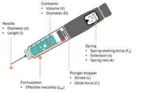
Figure 1: Illustration of autoinjector parameters for the definition of injection time, omitting losses in available force to bubble compression and friction.
Defining the parameters of an autoinjector
Consider an autoinjector (Figure 1) comprising a primary container with a liquid volume V and an internal diameter D. For illustration it is assumed that any bubble volume in the container vanishes once the container is pressurised, although this can be accounted for if needed. The liquid occupies a fraction of the container length L equivalent to the delivery stroke:

In this example the work required to deliver the drug is performed by the force of a compression spring which follows Hooke’s law, pushing on a rubber plunger stopper within the container:

Here F is the force at a particular instance during delivery, F0 is the force at the start of delivery, k is the spring constant and x represents the spring extension, which for simplicity is assumed to correlate to the plunger stopper displacement. The system generates pressure within the container, which due to the spring constant k diminishes as delivery progresses. This case is true for most autoinjectors powered by helical compression springs or gas springs. In the event of a system providing constant force such as an electronic driver or subliming substance, the delivery occurs at near steady state.
The force F exerted by the delivery system after accounting for frictional losses (glide force Ff) creates a pressure P within the container proportional to its cross-sectional area A. This produces a flow rate Q through the needle proportional to the hydrodynamic resistance of the needle (length and diameter) as well as the effective viscosity of the fluid. We assume here that no back pressure is present and therefore that P within the container is equivalent to ΔP across the needle.
Modelling non-Newtonian fluids
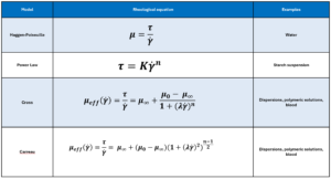
The viscosity and shear relationships for non-Newtonian fluids5,6 described by the power-law, Carreau and Cross fluid models are shown in Table 1.
Defining volumetric flowrate
The local velocity of the liquid in a needle depends on the distance r from the centre axis. Here a definition of volumetric flow rate adapted from a method attributed to Weissenberg, Rabinowitsch, Mooney and Schofield (WRMS)5,6 is used, and combined it with definitions for an autoinjector mechanism:

From this, an integral I is derived6. It is this integral that requires solving to determine the volumetric flow rate for a specific fluid model:

Substituting specific terms for τ and dτ followed by integration provides an analytical solution for a model of interest. In the case of a Newtonian fluid the results in the familiar Hagge-Poiseuille equation:

Non-Newtonian behaviour
It is useful to initially define power-law fluid behaviour, as it underpins both the Carreau and Cross fluid models. A power-law fluid flow profile is not parabolic (plug flow) and affects its volumetric flow rate at a given differential pressure. The magnitude of shear dependency is governed by a flow behaviour index (n), while the overall viscosity is regulated by the flow consistency index (K). Unlike the Cross and Carreau models, the power-law fluid equation for injection time can be analytically solved, as previously reported7. The normalized transition from parabolic to plug flow, as the value of n decreases, is illustrated in Figure 2.
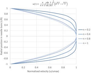
Figure 2 – Illustration of the change from a parabolic flow profile to plug flow for a power-law fluid with decreasing flow behaviour index n.
The analytical solution for injection time is found from the definition of the Power Law fluid volumetric flow rate:

Expanding for I and substituting container Diameter D for container radius R gives:

Where F is the applied force, D is the container diameter, d is needle diameter, l is needle length, K flow consistency index and n the flow behaviour index.
This is combined with the two equations describing the autoinjector to obtain a relation for plunger motion over time7 (note k for spring index is similar in appearance to K the flow consistency index):

For the purpose of integration this is simplified by introducing a constant C:
![]()
Integration over the stroke results in an analytical solution for injection time for a Power Law fluid from an autoinjector with a specific needle geometry and spring design:

Formulations with time-dependent non-Newtonian behaviour
Cross and Carreau are more complex, behaving as Power law fluid at intermediate rates and Newtonian fluids at both high and low shear rates (Figure 3). They require the definition of four-parameters including low-shear and high-shear viscosities , a characteristic time λ and a flow behaviour index n.

Figure 3 – Illustration of the Power law, Cross and Carreau apparent viscosity as a function of shear rate.
Finding an analytical solution as the one shown for a power-law fluid is not possible because the relationship between flowrate and pressure drop needs to be defined implicitly, requiring a numerical solver.
The two solutions start with the same definition from the WRMS method4,5 as before, where:

Carreau Fluid:
To solve the integral and calculate volumetric flowrate the equation defining viscosity for the Carreau fluid is introduced, substituting δ= (μ0–μ∞) and n -1 = n’ :

Substituting τ and dτ into the definition of integral I, changing the integration limits, and solving analytically results in a large equation (See reference [6] equation 30).
The only thing needed to calculate / is γ ̇w which can be obtained numerically using:

Cross Fluid:
The solution of a cross fluid is similar:

These are substituted into I and solved (See reference [6] equation 39 and 40). As with the Carreau model, only γ ̇w is required to do this numerically using the equation below:

Application to an autoinjector problem
In an autoinjector Q can be converted to the rate of change of the plunger position over time dx/dt, which correlates to an incremental reduction in available delivery force. The computation of injection time for Cross and Carreau fluids requires an incremental, numerical approach.
Initially the autoinjector system is considered at x = 0 and t = 0. The procedure is to starts with the determination of ΔP, I and finally flowrate Q at x(t=0) = 0 and F(x=0) = F0. Q is subsequently converted into a change of plunger stopper position over an increment. The new level of force at this spring extension is used to again calculate ΔP, , I and Q. Injection time is the sum of time intervals until the point where x = L, with smaller increments being preferable.
![]()
If the autoinjector supplies a constant force, the system can be treated as steady state over the interval from x=0 to x=L.
Determination of constants
The determination of the best fitting model as well as the relevant model parameters is achieved by fitting the models presented in Table 1 to data of log dynamic viscosity against the log of the shear rate. Solvers in programming languages such as MATLAB or Python as well as other commercially available rheology software can be used for this. Before analysing the data, it is important to consider if the experimental conditions cover a sufficiently large span of shear rates. This is to ensure that any Newtonian to non-Newtonian transitions are identified, and that the shear rates are representative of those experienced within an autoinjector.
Conclusion:
The models provided in this article are a step towards a common toolbox for drug delivery device design and process development. Understanding the non-Newtonian behaviour of formulations is essential for ensuring the efficacy and safety of advanced therapies. By embracing standardised modelling approaches and considering the complexities of non-Newtonian behaviour early in the development process, researchers and developers can de-risk future device development. This becomes more relevant as the industry focuses on established platform devices which may one day have to deliver increasingly more sophisticated formulations in the future.
Written by Alex Vasiev, Principal Engineer, and published in OnDrugDelivery.
References:
- Whitepaper: “The Rise of Biologics: Emerging Trends and Opportunities”, American Chemical Society, (2023).
- Baryakova, T.H., Pogostin, B.H., Langer, R. et al., “Overcoming barriers to patient adherence: the case for developing innovative drug delivery systems”. Nat Rev Drug Discov 22, 387–409 (2023).
- Debleena P., Gaurav S., Snehal S., Dnyaneshwar K., Kiran K., Tekade R.K., “Artificial intelligence in drug discovery and development.” Drug discovery today vol. 26,1 (2021): 80-93.
- Jindal A. B., Bhide A. R., Salave S., Rana D., Benival D., “Long-acting parenteral drug delivery systems for the treatment of chronic diseases”, Advanced Drug Delivery Reviews, (2023), Volume 198,
- A.H.P., “Non-Newtonian Flow and Heat Transfer”. John Wiley and Sons Inc., (1967).
- Sochi, T., “Analytical solutions for the flow of Carreau and Cross fluids in circular pipes and thin slits.” Rheologica Acta. (2015). 10.1007/s00397-015-0863-x.
- Vilaplana M., Vasiev A., White S., “Function-Based Primary Packaging Design for Injecting Viscous Non-Newtonian Formulations”. ONdrugDelivery Magazine, Issue 101 (Oct 2019), pp 20-25.